Using JMS Queue for message exchange in SOA 11G
JMS Queue Description:
Queue is a staging area that contains messages that have been sent and are waiting to be read. As the name queue suggests, the messages are delivered in the order sent. A message is removed from the queue once it has been read. It is point-to-point way of delivering messages. Only one consumer will get the message . The producer does not have to be running at the time the consumer consumes the message, nor does the consumer need to be running at the time the message is sent . Every message successfully processed is acknowledged by the consumer
4.
In Name
Your Project section provide Name
(JMSProducer).
Oracle JMS Adapter Types:
There are two ways of exchanging messages using JMS adapter.
1.
Using a Queue
which is a point to point interaction
for exchanging messages
2.
Using a Topic
which is a publish – subscribe model
for exchanging messages
In this blog we are going to see how to create and use JMS
Queue.
JMS Queue Description:
Queue is a staging area that contains messages that have been sent and are waiting to be read. As the name queue suggests, the messages are delivered in the order sent. A message is removed from the queue once it has been read. It is point-to-point way of delivering messages. Only one consumer will get the message . The producer does not have to be running at the time the consumer consumes the message, nor does the consumer need to be running at the time the message is sent . Every message successfully processed is acknowledged by the consumer
Creating a JMS Queue
in weblogic:
There are few steps involved in creating and using JMS Adapter.
1.
Creating JMS Topic or Queue
2.
Creating a Connection factory
3.
Creating anOutbound connection pool in the JMS Adapter
Prerequisites:
1.
Weblogicserver ,Oracle SOA Suite 11g and Oracle
JDeveloper should be installed and configured.
2.
Weblogic Admin Server should be up and running.
3.
If separate node manager is created for SOA, it
should be up and running.
4.
Oracle JDeveloper with SOA extension.
Creating JMS Queue:
1.
Login to weblogic console http://<host>:<port>/console
2.
In the domain structure , go to JMS Modules
Domain
Structure-><Domain Name> ->Services-> Messaging-> JMS Modules
3.
Click on JMS
Modules and in the Right pane Select the Module required. By default, SOAJMSModule will be available, In case for any user defined module
create one using New button under
JMS Module.
4.
Now under SOAJMSModule we are going to create a
new resource. We can create any one of the below resources for JMS .
i.
Connection Factory
ii.
Queue
iii.
Topic
iv.
Distributed Queue
v.
Distributed Topic
vi.
Foreign Server
vii.
Quota
viii.
Destination Sort Key
ix.
JMS Template
x.
SAF Imported Destinations
5.
To create above mentioned resources under the SOAJMSModule , click New button
6.
In the next page , choose the type of resource to be created.
7.
As we are going to create Queue , click on Queue and click Next
8.
Now JMS
Destination properties has to be provided. In the properties fill the
following
Name
: SampleQueue
JNDI Name: jms/SampleQueue
Template
: Leave Default
9.
Click Next to choose the Subdeployment. If a new / User defined Subdeployment should be
selected in the drop down list. If needed to be created use the Create a New Subdeploymentbutton to create one or leave the default
subdeployment(SOASubDeployment) and
click Finish.
10.
We will get a success message in the page.
Creating a Connection
Factory:
1.
Now a connection factory has to be created. For
that click New button in the JMS Resources Creation page.
2.
In the Resource selection page select Connection Factory and click Next.
3.
In the Connection properties provide the
following details
Name
:SampleCF
JNDI Name: jms/SampleCF
Rest others use the default ones and click Next.
4.
Now select the target to be deployed. Since only Admin server is there it has been
selected by default. If there are more targets (ie. Individual node managed
servers created / available) then select the appropriate target and click
Finish.
5.
Once done we will get a success message.
6.
After this we could be able to see the Queue and
Connection Factory in the JMS Modues.
Creating an Outbound
connection pool in the JMS Adapter:
1.
In the deployments
page click on JMS Adapter.
2.
In the next page , click on Configuration-> Outbound Connection Pools-> New
3.
Select the Outbound
connection Group and click Next.
4.
Provide the JNDI
Name. (eis/wls/SampleQueueCF)
5.
Now save the deployment Plan. If it is the first time deployment provide the
respective plane file to be updated . By default all the deployments will be
deployed to Plan.xml file. Choose the correct plan file and click Ok .
6.
We will get a success message after the
deployment.
7.
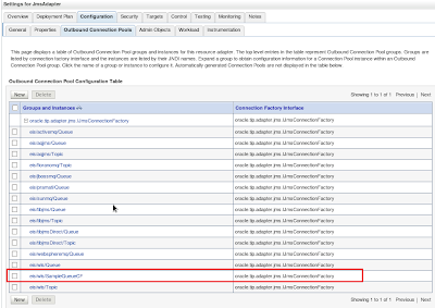
Now click Configuration
->Outbound Connection Pools and expand the oracle.tip.adapter.jms.IJmsConnectionFactory. The created
Connection pool will be available with name eis/wls/SampleQueueCF.
8.
Click on that and provide the appropriate
connection factory name in the Connection
Factory Location column with the connection factory JNDI name
(jms/SampleCF) and press enter key in
keyboard and click Save.
9.
A success message will be displayed in the next
screen.
10.
Now the adapter should be updated with the
modifications. So Click Deployments
and select JMSAdapter and click Update.
Note: Click Lock and Edit button in the left pane as we are going to update the
details to weblogic.Once done click Release
Configuration.
11.
Select Update
this application option and click Next.
12.
Click Finish
in the next page.
13.
After this we will get success message.
Now we are ready to create JMS related
interfaces using JMS Queue.
JMS Adapter Message exchange Types:
There are two different ways to use the JMS Queue for
exchanging messages.
1.
Produce
and Consume way of exchanging messages
2.
Request-Reply
way of exchanging messages.
A.
Produce/Consume Type:
Creating a new SOA Application:
1.
Open JDeveloper
and create a new Application
2. File->New
3.
In the Categories on left side, select General->Applications and in the
Items on right side select SOA Application.
4.
In the Application
Name section provide the Name (SampleJMSApplication) and provide the
directory where the application code and its contents should be placed and
click Next.
5.
Next there will be a section for creating New
project . If the project should be created there itself use it (Please see the
steps for creating a project in the next steps).
6.
Click Finish.
If the project should be created later.A sample project will be created in the above step by default.
Creating a new SOA
project:
1.
In the left pane in the Application Navigator Drop
Down select the application under which the project should be created.
2.
Right click on the Application and Select New Project.
3.
In the next window on the left pane under Categories select Projects
and in Right pane under Items select
SOA Project.
For Directory choose the path
where the project files should be created.
In
the Project Technologies section
select SOA and move it to Selected section using the Right Arrow and click Next.
5.
In the next page select the template. Choose Empty Composite and click Finish.
Using
the above steps create a project for JMS
Producer.
Creating an
Application server for Adapter or Deployment configuration:
1.
Now click the Green Plus icon in the AppServerConnection
to create a new Application server.During Adapter Creation
During Deployment
2.
Provide name
for the application server and click Next.
3.
Provide username
and password for the application server and click Next.
4.
Provide
Hostname , Port and Domain details in the page and click Next.
5.
Now test the connection by Clicking Test Connection button.
Note: Check whether all the tests are successful else check
the domain or port or hostname is correct.
6.
Once tests are successful click Next and in the
next page click Finish.
Steps for Deploying a
SOA process:
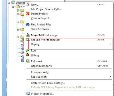
i.
Right click on the Project to be deployed and go
to Deploy option.
ii.
In the option the project to be deployed will be
displayed. Select the project.
iii.
In the deployment option select Deploy to
Application Server and click Next.
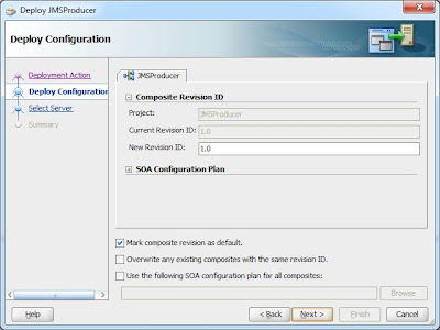
iv.
Leave default options and click Next.
v.
In the next page select or create the
application servers where the project has to be deployed. If already exists
select the Application server connection and click Next or Click Green Plus
icon to create one. (Same steps as in section
vi.
Provide the Application server name and click
Next.
vii.
Provide the username and password for the server
and click Next.
viii.
Provide the application server host name or ip,
port in which application server is running and the domain where the project has
to be deployed and click Next.
ix.
Test the connection and check all the items are
successful in connecting with the server and click Next or Finish.
x.
Click Finish to complete the application server
creation steps.
xi.
Now select the application server where the
project has to deployed and click Next.
xii.
Now select the partition where the project has
to be deployed and click Next.
xiii.
Click Finish to complete the deployment steps.
xiv.
Now in the deployment log from the Jdeveloper,
we could see the project has been deployed.
JMS Producer:
Note: XSD used in the
following project is in below snapshot.
<?xml version = '1.0'
encoding = 'UTF-8'?>
<xs:schema
xmlns:xs="http://www.w3.org/2001/XMLSchema"
elementFormDefault="qualified" attributeFormDefault="unqualified"
targetNamespace="http://xmlns.oracle.com/singleString">
<xs:element name="singleString"
type="xs:string"/>
</xs:schema>
1.
In the composite.xml file drag a mediator component into the Components
Section.
2.
In the next section provide the name and select
the template for the Mediator.
·
Name:
JMSProducerMediator
·
Template:
One-Way Interface
·
Check
the option Create Composite Service with
SOAP Bindings
·
Click OK
3.
Now the Mediator with SOAP Bindings is created
in the composite.
4.
Now from the Component Palette under Service
Adapters section Drag and drop JMS Adapter.
JMS Adapter
Configuration Wizard:
5.
In the welcome screen click Next.
6.
Click Next
and in the next section provide JMS
Adapter Name in the Service Name
and click Next.
7.
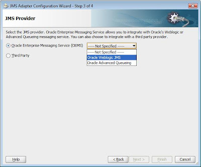
Now select the JMS Provider .Since the one we
are using is the Oracle Weblogic server
and its JMS select Oracle Enterprise
Messaging Services (OEMS) and in the drop down select Oracle Weblogic JMS.
8.
In the next page we have to create or choose the
service connection of the application server where JMS is running. In the flow
either select already existing one or create new application server using the
steps in the Creating an Application
server for Adapter or Deployment configuration section.Once application
server is created we will be back to the JMS adapter configuration wizard with
the connection selected in dropdown list. Select required Application server
connection and click Next.
9.
Click option Define from operation and schema (specified later) as we are going
to define the schema later and click Next.
10.
In the operation section select Produce Message option and click Next.
11.
In the next section we have to provide the Produce Operation Paramters.
12.
For selecting the message click Browse Button and in the options listed
select the destination queue.
13.
After the queue selection provide the JNDI name
what has been configured in console. In our case it is eis/wls/SampleQueueCF.
If needed change the default options for the Priority ,Time to live, Delivery
Mode, Message Type and click Next.
14.
Now select the schema for the message to be
produced.Use the search icon.
15.
Select the schema file from the project file browser popup and
click OK.
16.
Click Next.
17.
Click Finish.
18.
Now in the Application Navigator we could see
the .wsdl and .jca files created for the Adapter.
19.
Now wire the mediator to the JMS Adapter.
20.
Now double click the Mediator
(JMSProducerMediator) or double click the .mplan file.
21.
Now to create a new mapping from the input to
JMSAdapter click on the Transform Using
option.
22.
Now click on Create New Mapper File
23.
An xsl file is created with the above mentioned
file name under xsl folder of the project.
24.
Now the source node has to be mapped to the
target node . for this drag and drop from source to target element.
25.
Now the mapping file will be available in the
Transform using section on the routing rule.
Now save all and follow the deployment procedures in the Steps for Deploying a SOA process section.
Checking:
I.
Now we could do the checking and testing of the
process that we have deployed.
III.
Now check whether the process has been deployed
under the right domain and right partition.
Testing:
Now we will check whether the messages are being published
to JMS .
2)
Goto the process <Domain> -> SOA -> soa-infra -> <Partition>
-> <Process> and click the process that we have deployed. JMSProducer.
3)
In the right hand side click Test button
5)
Once the run is completed we could see Launch
Flow Trace option . click that for checking the flow trace.
6)
A popup window displaying the flow trace will be
displayed .
Note: Normally popups will be
disabled. So in case if you are not able to see the popups please check your
browser and enable the popups.
7)
Now we have to check whether the message has
been published to JMS Queue.
9)
Browse to JMS Modules : Domain Structure -> < Domain> -> Services
-> Messaging -> JMS Modules and in the right side click on SOAJMSModules.
10)
Now we have to see the messages published.Click
tab Monitoring -> Select the SOAJMSModule!SampleQueue -> click Show
Messages.
12)
We would be able to see the message displayed.
JMS Consumer:
i.
Create a new project for JMS Consumer.
ii.
Right click on the application and select New
Project.
iv.
Provide the name in Project Name, select the
path where the project should be placed
in Directory and in the Project Technologies select SOA and move it to
Selected tab using the Right arrow mark and click Next.
ix.
In the JMS Provider section select Oracle
Enterprise Messaging Services(OEMS) and in the dropdown select Oracle
Weblogic JMS.
xi.
Select the Application server connections for
selecting the JMS queue. If no server is created create one . Please refer to Creating an Application server for Adapter or
Deployment configuration section.
xii.
In the adapter interface section select Define
from operation and Schema (Specified Later) for the Interface and click Next.
xvi. Provide
the JNDI Name (eis/wls/SampleQueueCF).If required configure the Message type,
Messgae selector ( kind of condition to pick the messages which satifies the
condition).Click Next .
xvii. Now in the messages section select the schema
.Click the search button to search and select the schema file.
xviii.
Since we don’t have the schema file we will
import it from the previous project (JMSProducer) for this in the Type chooser
select the option to Import Schema file.
xx.
In the SOA Resource Browser select the File
System in the dropdown and choose the file and select ok.
xxii.In Localize files option
uncheck the Maintain original directory structure for imported files and click
OK.
xxvii.
In the Components section drag and drop BPEL
Process from the Service components section of Component Palatte.
xxviii.
In the create BPEL Process page do the
following.
Name
:provide the name
Template:Select One Way BPEL Process
Uncheck Expose as a SOAP Service.
xxxi.
Now double click on the BPEL (BPELConsumer) and
right click on the wire between bpelconsumer_client and receiveInput and select
Delete and confirm it.
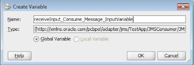
xxxiv.
In the next popup leave the default variable
name or if needed change as per the requirement and click OK.
xlii. Now
assign recevieInput_Consume_Message -> body -> ns2:singleString from
Input to Output -> ns2:singleString and click OK.
xliii. Now
save all and deploy the process. Please refer to the deployment steps in Steps
for Deploying a SOA process section above.
xliv.Check the process has
deployed properly as in the Checking
section above.
Testing:
a)
Since the JMSAdapterConsumer is of polling type
whenever a message is available in the queue it will be polled.
b)
Login to EM http://<host/ip>:<port>/em
c)
Goto the process JMSConsumer under
<Domain> -> SOA -> soa-infra -> <partition>
f)
From the popup window above click on BPELConsume
BPEL Component and in the message flow
click receiveInput icon or activity trial click View XML Document.
So in the above section you could have got an idea how to use the Produce-Consume type JMS adapters.
Now we will see how to use Request Reply type JMS message exchange.
Now we will see how to use Request Reply type JMS message exchange.
B.
JMS Request Reply
Note: XSD used in the
following project is in below snapshot.
<?xml version = '1.0'
encoding = 'UTF-8'?>
<xs:schema
xmlns:xs="http://www.w3.org/2001/XMLSchema"
elementFormDefault="qualified"
attributeFormDefault="unqualified" targetNamespace="http://xmlns.oracle.com/singleString">
<xs:element name="singleString"
type="xs:string"/>
</xs:schema>
1.
Create the new project for the request reply
process using the following steps.
2.
In the Jdeveloper Application Navigator Select
the application under which the project should be created and click New
Project.
3.
In the next page select Projects from Categories
pane and SOA Project in the Items from the right pane and click OK.
4.
In the Name your Project section provide the
Name and Select the folder structure where the project files should be created
and in the Project Technologies section select SOA and move to the Selected
section using the right arrow mark and click Next.
5.
In the next section select the composite
template. For now select Empty composite and click Finish.
7.
Drag and drop JMS Adapter from the Services
section of the Component Palatte into the External References pane.
10.
In the JMS Provider section select the Oracle
Enterprise Messaging service and in the drop down select Oracle Weblogic JMS.
12.
Now in the service connection wizard either
select the application server which already got created or create a new one.For
creating new Application server follow the steps in the Creating an Application server for Adapter or Deployment configuration
section.Once done select the application server.
14.
In the Adapter Interface section select the Define from operation and schema (specified
later) and click Next.
15.
In the operation section select
Request/Reply and Operation Name select
Asynchronous and click Next.
20.
Click Brose for Destination Name and from the
popup select the queue and click OK.
Note: For sample i have used the same queue for both request
and reply . We can use different queues as well.
22.
In the messages section select the message type
from the xsd file for both request and reply using the search icon.
25.
Now drag and drop BPEL Process in the Service
components of the Component Palatte to
the Components section.
26.
Provide the Name for the BPEL process , select
Asynchronous BPEL Process in the Template , Check Expose as a SOAP service
option and click OK.
29.
Now double click on the BPELReqReply BPEL
component . We could see the .bpel file opened with default receive callback
section.
30.
Now drag and drop Invoke activity from Component
Palatte -> BPEL Constructs -> Web Service after the receiveInput.
31.
Wire the Invoke activity to JMS Adapter
JMSReqReply. By default a popup for Editing the invoke appears.
32.
In the General tab of the Edit Invoke popup
provide the name and create new variable by clicking the Green plus icon in the
Variables -> Input section.
35.
Now drag and drop Receive activity from the
Component Palatte -> Web Services -> BPEL Constructs after the Invoke
activity.
37.
In the Edit receive popup provide the Name in
General tab and create new variable by clicking the Green plus icon in the Name
Variable.
40.
Now drag and drop Assign activity from Component
Palatte -> BPEL Constructs -> Activities -> Assign in between
receiveInput and Invoke activity.
42.
In copy rules section of the Assign map
From : Variables -> Process ->
Variables -> inputVariable -> Payload -> client:process ->
client:inputString
To: Variables-> Process ->Variables
->InvokeRequest_Request_Input_Variable-> singleString ->
ns2:singleString
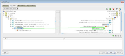
46.
Double Click on assign activity and map the
following.
From : Variables ->
Process->Variables->ReceiveReply_Reply_InputVariable->singleString->ns2:singleString.
48.
Click Save all.
49.
Now deploy the process (Refer Steps for Deploying a SOA process section).
Testing:
11.
In the outcoming popup we could see the output
with the message we have given as input.














Comments
Post a Comment